1. Architectural & Thermodynamic Deep-Dive into IC411 Cooling Topology
In modern power generation, heavy refining, continuous processing, and large-scale mining, the selection of high voltage motor cooling topologies dictates long-term thermal stability, mean time between failures (MTBF), and overall life-cycle expenditure (LCOE). Under the IEC 60034-6 standard, cooling designations define the circuit arrangement and the methods used to transport heat away from active electrical components (stator windings and rotor cores).
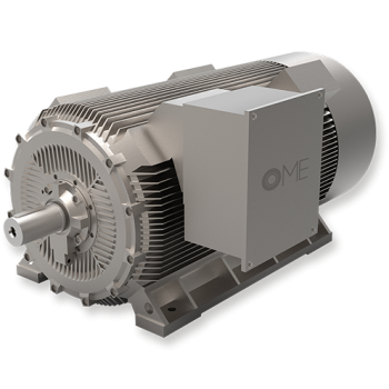
The IC411 cooling code (equivalent to NEMA Totally Enclosed Fan Cooled - TEFC) represents one of the most robust, self-contained, and structurally resilient cooling architectures available for high-voltage industrial induction motors.
Circuit Code: IC4 (Internal)
The primary cooling medium (internal air) circulates within a fully closed loop, driven by internal rotor fins or internal shaft-mounted fans, absorbing energy dissipated by stator copper losses ($I^2R$) and core iron losses.
Circulation Code: 1 (External)
The secondary cooling medium is ambient air driven across the external surface of the motor frame. Heat transfer occurs conductively through the cast-iron housing and convectively into the external airstream.
Drive Mechanism: 4 (Shaft-Driven)
The external cooling fan is mounted directly on the non-drive end (NDE) motor shaft, ensuring that cooling air delivery dynamically scales with motor rotational speed without requiring external electrical power supplies.
Thermodynamic Physics of Surface Cooling in IC411 High Voltage Frames
Unlike heat-exchanger-topped motors (such as IC611 air-to-air or IC81W air-to-water units), an IC411 High Voltage Motor relies entirely on conductive heat dissipation through its structural enclosure, supplemented by external longitudinal cooling ribs. The thermal flux equation governing this dissipation is defined as:
Fundamental Heat Transfer Model for Ribbed IC411 Housings:
Q_total = h_conv · A_eff · (T_surface - T_ambient) + ε · σ · A_rad · (T_surface^4 - T_ambient^4)
Where A_eff represents the extended heat-exchange surface area provided by aerodynamic longitudinal casting fins, and h_conv is the forced convection coefficient governed by the boundary layer velocity of the shaft-driven non-sparking external fan.
To maximize A_eff without inducing structural resonant vibrations under heavy torque fluctuations, OME Motors utilizes high-grade cast-iron housing alloys (EN-GJL-300 or ductile EN-GJS-400-15). The frame geometry features optimized aerodynamic fin spacing calculated using Computational Fluid Dynamics (CFD) to prevent boundary layer separation and dust accumulation in desert or cement plant environments.
| Cooling Code (IEC 60034-6) | NEMA Equivalence | Cooling Mechanism | Maintenance Profile | Environmental Tolerance | Ideal Power Output Range |
|---|---|---|---|---|---|
| IC411 | TEFC (Frame Surface Cooled) | Internal closed-loop air; external shaft fan blowing over ribbed frame | Lowest: No heat exchanger tubes to clean or purge; inspect fan cowl only | Highest: Immune to external dust, humidity, slurry, ambient salt spray | 160 kW to 2,000 kW (Frame 355 to 630) |
| IC611 | TEAAC (Air-to-Air Exchanger) | Internal air routed through top-mounted tube heat exchanger cooled by external fan | Moderate: Periodic cleaning of internal cooling tubes required | High: Enclosed loop, but top exchanger increases physical height/footprint | 1,000 kW to 10,000+ kW |
| IC81W | TEWAC (Air-to-Water Exchanger) | Internal air recirculated through water-chilled tube heat exchanger core | High: Demands pure cooling water infrastructure, leak detection, flow monitoring | Restricted: Requires continuous plant cooling water loops | 2,000 kW to 25,000+ kW |