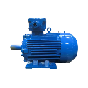
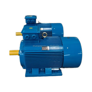
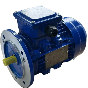
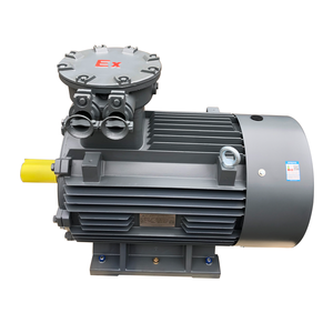
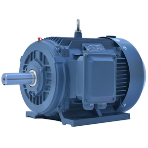
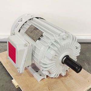
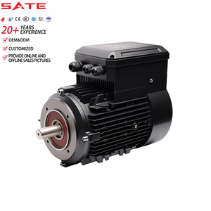
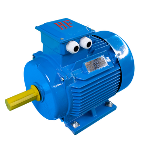
In modern industrial power transmission, the integration of Variable Frequency Drives (VFDs) and Pulse Width Modulation (PWM) inverters has revolutionized energy efficiency and process control. However, driven by fast-switching Insulated Gate Bipolar Transistors (IGBTs), standard AC induction motors often experience severe dielectric, thermal, and mechanical stress when operated under open-loop or closed-loop inverter power.
As an established Italian industrial electric motor manufacturer with over 50 years of heritage (inheriting the electromechanical mastery of O.M.E. Motori Elettrici s.r.l.), we specialize in custom OEM engineering solutions tailored specifically to withstand the grueling electrical dynamics of VFD operation. This technical guide outlines the critical engineering parameters involved in selecting and customizing Inverter Duty Electric Motors for heavy industry, mining, petrochemical plants, steel mills, and marine systems.
When a VFD synthesizes a sine wave via PWM, it generates thousands of voltage pulses per second with extremely steep rise times ($dV/dt$), often exceeding 5,000 to 10,000 Volts per microsecond ($\mu s$). Over long cable runs between the drive and the motor, these steep voltage fronts cause impedance mismatches, resulting in reflected wave phenomena that double the peak voltage at the motor terminals ($V_{peak} \ge 2.2 \times V_{nominal}$).
Standard stator insulation systems suffer rapid partial discharge (corona breakdown), leading to inter-turn short circuits and premature motor burnout. To overcome this, our custom OEM inverter duty motors utilize:
PWM inverters introduce a high-frequency neutral point voltage relative to ground, known as Common-Mode Voltage (CMV). This voltage capacitively couples from the stator winding to the rotor shaft, seeking the path of least resistance to ground through the motor bearings.
Discharge machining currents ($EDM$) arc across the lubrication film, creating micro-spalls and cratering ("fluting") on bearing raceways, causing premature mechanical collapse.
Non-conductive Silicon Nitride ($Si_3N_4$) ceramic balls provide total galvanic isolation, interrupting the shaft current path completely for frames 280 and above.
Maintenance-free conductive micro-fiber grounding rings safely channel shaft voltage directly to the motor frame, bypassing bearing raceways safely.
A standard Totally Enclosed Fan Cooled (TEFC - IC411) motor relies on its shaft-mounted fan for cooling. When driven by a VFD at low operational speeds (e.g., 5 Hz to 20 Hz for constant torque loads like positive displacement pumps or extruders), fan velocity drops linearly, reducing cooling airflow by the square of the speed ($\text{Airflow} \propto RPM^2$). This leads to rapid thermal buildup.
| Motor Engineering Parameter | Standard General Purpose Motor | Custom OEM Inverter Duty Motor (OME Motors) |
|---|---|---|
| Insulation Class & Rise | Class F ($155^\circ\text{C}$), Class B rise | Class H ($180^\circ\text{C}$), VPI Treated Corona Proof Wire |
| Inverter Compliance Standard | IEC 60034-17 (Basic variable speed) | NEMA MG1 Part 31 & IEC 60034-18-41 |
| dV/dt Transient Peak Rating | Up to 1,000V @ $1.0\,\mu s$ rise time | Up to 2,200V @ $0.1\,\mu s$ rise time ($V_{peak}$) |
| Constant Torque Turndown Ratio | 4:1 Speed Range (TEFC IC411) | 1000:1 (Closed Loop) with IC416 Forced Blower System |
| Bearing Protection System | Standard Steel Bearings (Uninsulated) | Insulated NDE Bearing + Shaft Grounding Ring (Aegis/SGL) |
| Hazardous Area Rating | Safe Area Only | ATEX / IECEx / Ex d / Ex db / Ex eb / Zone 1, 2, 21, 22 |
As industrial OEMs transition toward Smart Manufacturing (Industry 4.0) and stringent zero-carbon compliance guidelines, procurement managers are rethinking total cost of ownership (TCO). Electrical energy accounts for over 90% of an electric motor's lifetime cost, making motor efficiency and VFD optimization the paramount criteria for global equipment manufacturers.
Global regulations (such as EU Ecodesign Directive 2019/1781) enforce strict minimum efficiency limits. OEM procurement is rapidly moving toward Permanent Magnet Synchronous Motors (PMSM) and Synchronous Reluctance Motors (SynRM) which maintain IE4 and IE5 efficiency curves even under partial load VFD operations.
Modern OEM motor specifiers demand integrated sensor ports for wireless vibration analysis, temperature RTDs embedded in stator windings (PT100/PTC), and acoustic emission tracking. This enables real-time motor health monitoring directly back to the master SCADA or cloud system.
Industrial machinery builders require flexible, plug-and-play mechanical configurations. Custom shaft extension dimensions, double shaft ends, specialized flange orientations (B3, B5, B35, V1, NEMA C-Face/D-Flange), and custom paint/corrosion resistance classes (C3 to C5-M for offshore marine) are standard requirements for OEM supply chains.
Combining 50+ years of Italian electromechanical engineering with state-of-the-art testing facilities in Gussago and Nuvolera, Italy, OME Motors delivers tailored electric motor solutions engineered for non-stop performance. From heavy-duty mining crushers and oil refinery pumps to high-speed compressors, our custom OEM inverter duty motors meet ATEX, IECEx, NEMA, UL, CSA, and GOST international standards.