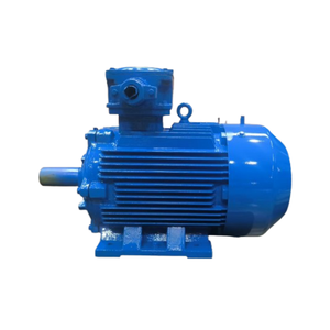
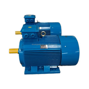
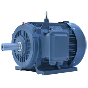
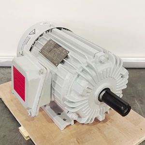
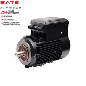
Explore our top-tier industrial electric motors engineered specifically to withstand carrier frequency harmonic voltage spikes, PWM wave stress, and continuous variable speed torque loads.
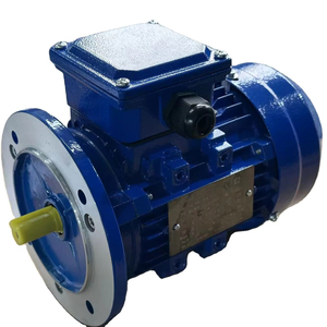
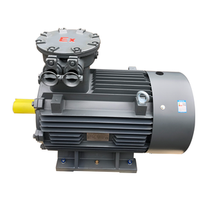
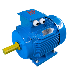
In modern industrial automation, integrating Variable Frequency Drives (VFDs) or Variable Speed Drives (VSDs) with three-phase electric motors represents the baseline for achieving superior energy control, precise torque modulation, and operational decarbonization. However, operating standard mains-supplied asynchronous motors directly on Pulse-Width Modulated (PWM) inverter waveforms exposes stator windings and mechanical bearing assemblies to extreme stress phenomena that traditional AC induction motors were never designed to sustain.
Leading Chinese VFD motor manufacturers have fundamentally revolutionized stator insulation, magnetic core geometry, thermal management systems, and bearing protection strategies to engineer specialized Inverter-Duty Motors conforming strictly to IEC 60034-18-41/42 and NEMA MG1 Part 31 standards.
Information Gain Insight: Operating a standard mains motor on a VFD can cause premature stator winding breakdown within 6 months due to reflected wave voltage peaks (up to 2.5x rated voltage) and shaft voltage discharges. Purpose-built VFD motors utilize Class H Corona-Resistant spike-guard magnet wire paired with Vacuum Pressure Impregnation (VPI) to deliver an extended operating life exceeding 20 years under harsh PWM switching frequency regimes.
When selecting a supplier from a leading Chinese motor factory, industrial procurement teams must verify that the motor design neutralizes the three core failure vectors triggered by modern IGBT/SiC-based frequency converters:
High carrier frequencies (4kHz to 16kHz) combined with fast IGBT switching rise times (dV/dt > 5000 V/µs) create voltage reflection along long motor leads. Our VFD motors utilize dual-film corona-resistant enamel wire rated to withstand peak surges up to 1600V with rise times < 0.1 µs.
Common-mode voltage induced by VFDs causes high-frequency circulating currents through motor bearings, resulting in fluting, micro-welding, and mechanical noise. We integrate hybrid ceramic insulated bearings at the non-drive end and AEGIS® conductive shaft grounding rings at the drive end.
When operated at low speeds (e.g., 5 Hz to 20 Hz) for constant torque loads (extruders, positive displacement pumps), shaft-driven internal fans lose cooling velocity exponentially. Our inverter-duty motors feature IC416 force-ventilated auxiliary cooling blowers to ensure 100% continuous torque rating from 0 RPM.
As global industrial supply chains realign around technical competence, certified quality control, and cost competitiveness, premier Chinese motor manufacturers have established world-class production ecosystems. Combining European design methodologies (incorporating advanced finite element electromagnetic modeling) with fully automated, high-precision manufacturing infrastructure, China’s top-tier factories lead the world in high-efficiency electric motor production volume and customized engineering agility.
Our state-of-the-art manufacturing facilities in Brescia-partnered and Chinese industrial bases integrate complete vertical integration—from cold-rolled silicon steel lamination punching to automated robotic slot insulation insertion, VPI processing, dynamic balancing, and full-load VFD testing benches:
| Manufacturing & Process Benchmark | Standard Commercial Grade Motors | Our Advanced VFD Inverter-Duty Motors | Operational Impact for Buyer |
|---|---|---|---|
| Magnet Wire Grade | Class F Grade 1 Polyurethane Enamel | Class H Corona-Resistant 200°C Dual-Coated Wire | Eliminates insulation partial discharge failures under high PWM carrier frequency. |
| Stator Impregnation Process | Conventional Dip & Bake Varnish | Automated Vacuum Pressure Impregnation (VPI) | Void-free resin fill, superior heat dissipation, and IP55/IP56 environmental sealing. |
| Bearing Protection System | Standard Steel Ball Bearings | Insulated Non-Drive End Bearing + Shaft Grounding Ring | Prevents bearing micro-fluting; extends lubrication and mechanical service interval up to 50,000 hrs. |
| Cooling System Topology | IC411 Self-Ventilated Shaft Fan | IC416 Independent Powered Auxiliary Blower Fan | Allows continuous zero-speed operation under 100% full rated torque without overheating. |
| Dynamic Rotor Balance | Grade G2.5 ISO 1940 Compliance | Grade G1.0 Precision Dynamic Balancing | Minimizes structural vibration harmonics, reducing mechanical strain on gearboxes and pumps. |
Procurement directors and plant managers must evaluate upcoming technological shifts when placing long-term enterprise purchase orders. The global industrial motor ecosystem is undergoing a generational shift driven by stringent energy efficiency directives (such as the EU Ecodesign Regulation 2019/1781) and smart manufacturing digital transformation.
While IE3 (Premium Efficiency) motors served as the global baseline for a decade, forward-thinking enterprises are rapidly transitioning to IE4 (Super Premium) and IE5 (Ultra Premium) Permanent Magnet Synchronous Motors (PMSM) and Permanent Magnet-Assisted Synchronous Reluctance Motors (PM-SynRM). PMSM VFD motors eliminate rotor copper losses completely, achieving up to 97.2% systemic efficiency across dynamic variable speed speed-load profiles.
The rise of wide-bandgap Silicon Carbide (SiC) power electronics enables VFDs to switch at frequencies above 20 kHz with negligible switching losses. Chinese factories are pioneering ultra-low inductance, high-frequency VFD motors optimized specifically for SiC drives, yielding ultra-compact drive-motor packages with minimal harmonic noise emission.
Procurement specs now increasingly demand factory-installed smart diagnostic sensors. Our next-generation VFD motors come equipped with tri-axial wireless vibration monitors, winding temperature RTDs (Pt100), and bearing thermal sensors that stream real-time operational telemetry into cloud-based Predictive Maintenance (PdM) platforms, virtually eliminating unplanned downtime.
Detailed technical responses curated by our chief electrical application engineers to resolve critical procurement, engineering sizing, and installation inquiries.
A standard AC motor is optimized for fixed-frequency sinusoidal mains power (50/60Hz). When powered by a VFD, non-sinusoidal PWM voltage pulses create voltage spikes (reflected waves), high thermal heating from harmonics, and bearing discharge currents. A true VFD-duty motor utilizes corona-resistant Class H insulation, VPI treatment, IC416 forced ventilation, dynamic rotor balancing, and insulated/grounded bearing protection to operate reliably under variable speeds and pulse waveforms.
The selection depends on the load profile and speed range. For variable torque loads (like centrifugal pumps and fans), power and torque requirements drop cubically/quadratically with speed reduction, so an IC411 motor is usually sufficient. For constant torque loads (such as extruders, positive displacement pumps, cranes, and conveyors) operating below 50% rated speed (e.g., 5 Hz to 25 Hz), the internal shaft fan of an IC411 motor cannot generate sufficient airflow. An IC416 motor with an independent electric blower fan must be specified to prevent thermal trip failures.
To prevent high-frequency shaft voltages created by common-mode VFD switching from causing electrical discharge machining (EDM) in bearings, leading factories employ a two-part system: (1) An electrically insulated bearing (coated with aluminum oxide ceramic or equipped with ceramic rolling elements) installed at the Non-Drive End (NDE) to break the circulating current path, and (2) A conductive micro-fiber shaft grounding ring (e.g., AEGIS® or equivalent) at the Drive End (DE) to safely divert shaft charges away from the driven equipment.
Yes, but with strict operational constraints. To prevent insulation damage, the cable distance between the VFD and motor should be minimized (< 20 meters), or a dV/dt filter / sine-wave filter must be installed at the inverter output. Furthermore, the motor speed range should be restricted (typically 20 Hz to 50 Hz for constant torque), and a thermal derating factor of 10% to 15% must be applied to account for harmonic heating losses.
For European market compliance: CE marking, IEC 60034 series adherence, and EU Ecodesign IE3/IE4 efficiency compliance are mandatory. For explosive environments, ATEX (Directive 2014/34/EU) and IECEx certifications are strictly required. For North America: UL listing, CSA certification, and NEMA MG-1 Part 31 compliance for inverter duty, along with US Department of Energy (DOE) efficiency registration, are necessary.
Standard IE3/IE4 VFD motors in stock frames (80M to 355L) ship within 7 to 14 business days. Customized industrial motors—such as high-voltage medium-speed motors, custom mounting flange configurations (B35/B5/V1), special shaft extension dimensions, marine-grade IP66 stainless steel construction, or hazardous area explosion-proof specs—typically feature a manufacturing lead time of 25 to 40 days, complete with factory acceptance testing (FAT) reports.
Partner with China's premier inverter-duty motor manufacturer. Send us your motor frame sizes, voltage ratings, speed ratios, and application parameters to receive factory-direct engineering support and volume pricing.